 E-mail: sales1@rlbcable.com
 English
 العربية
 Le français





Wire drawing and Cable Extrusion: Process and Quality Control
 Oct 29, 2026|
 View:1
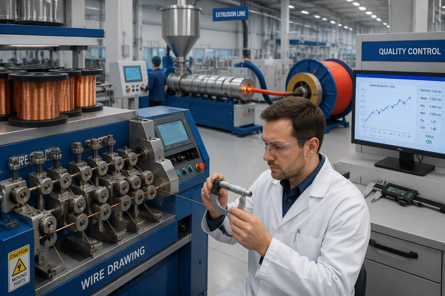
Wire drawing is a cold working process. A metal rod is pulled through a tapered die to make it thinner. Cable extrusion pushes melted polymer through a die around the conductor. Both stages are part of the five-stage wire and cable manufacturing chain: drawing, annealing, twisting and stranding, extrusion coating, and cabling. Each stage builds on the one before it.
These two processes shape conductor geometry, conductivity, surface finish, and insulation integrity. Together they decide cable performance, safety, and reliability. This reference explains each process step by step and the quality control used at every stage, including key parameters, common defects, and testing methods. Making high-quality cables depends on disciplined control of both wire drawing and cable extrusion.
Key Takeaways
Wire drawing makes metal thinner by pulling it through dies. Cable extrusion puts melted plastic around the wire. Both steps are very important for cable quality.
Control the reduction ratio and die design in wire drawing. This stops defects like cracks and breaks.
In cable extrusion, keep the melt temperature and cooling steady. This prevents rough surfaces, bubbles, and weak insulation.
Use inline monitoring and lab tests at every stage. Find problems early to save time and money.
Pick materials and processes that work well together. This makes sure the final cable is reliable and safe.
Wire Drawing and Cable Extrusion Overview
The Five-Stage Production Chain
Wire and cable manufacturing follows a set order. Each stage gets the workpiece ready for the next one:
Wire drawing pulls metal rod through smaller and smaller dies until it reaches the target diameter.
Annealing brings back the ductility that cold working has used up.
Twisting and stranding builds flexible conductors from individual wires.
Extrusion coating puts insulation or sheathing around the conductor.
Cabling puts the finished cores together into the final cable construction.
Drawing comes early in this chain. It turns cast rod into wire of the required gauge before annealing and stranding. Cable extrusion comes at the end. The bare stranded conductor enters the extruder line, where polymer pellets melt, pressurize, and flow through a crosshead die to form the insulation jacket. People often call the extruder the most capital-intensive equipment on a wire and cable production line. It mostly decides insulation wall consistency, surface quality, and compliance with electrical standards.
Why Each Stage Matters
Wire drawing improves conductivity and surface finish for solid wires. A clean, even surface helps later stages bond and conduct reliably. Cable extrusion then applies the insulation or jacket that protects the conductor. The cable making process depends on both stages working together.
A defect introduced at any stage can travel through thousands of meters of continuous product before anyone finds it. Quality control must therefore happen at every step, not only at final inspection.
Problems at either stage carry downstream. A wrong draw reduction ratio or a miscalibrated extrusion line harms electrical performance, mechanical durability, or compliance with standards such as IEC 60228. Poor temperature control during extrusion causes melt viscosity fluctuations, which produce wall thickness variation and spark test failures. The lesson is simple: wire drawing and cable extrusion set the quality ceiling for the whole line.
Wire Drawing Fundamentals
Drawing Principles and Reduction
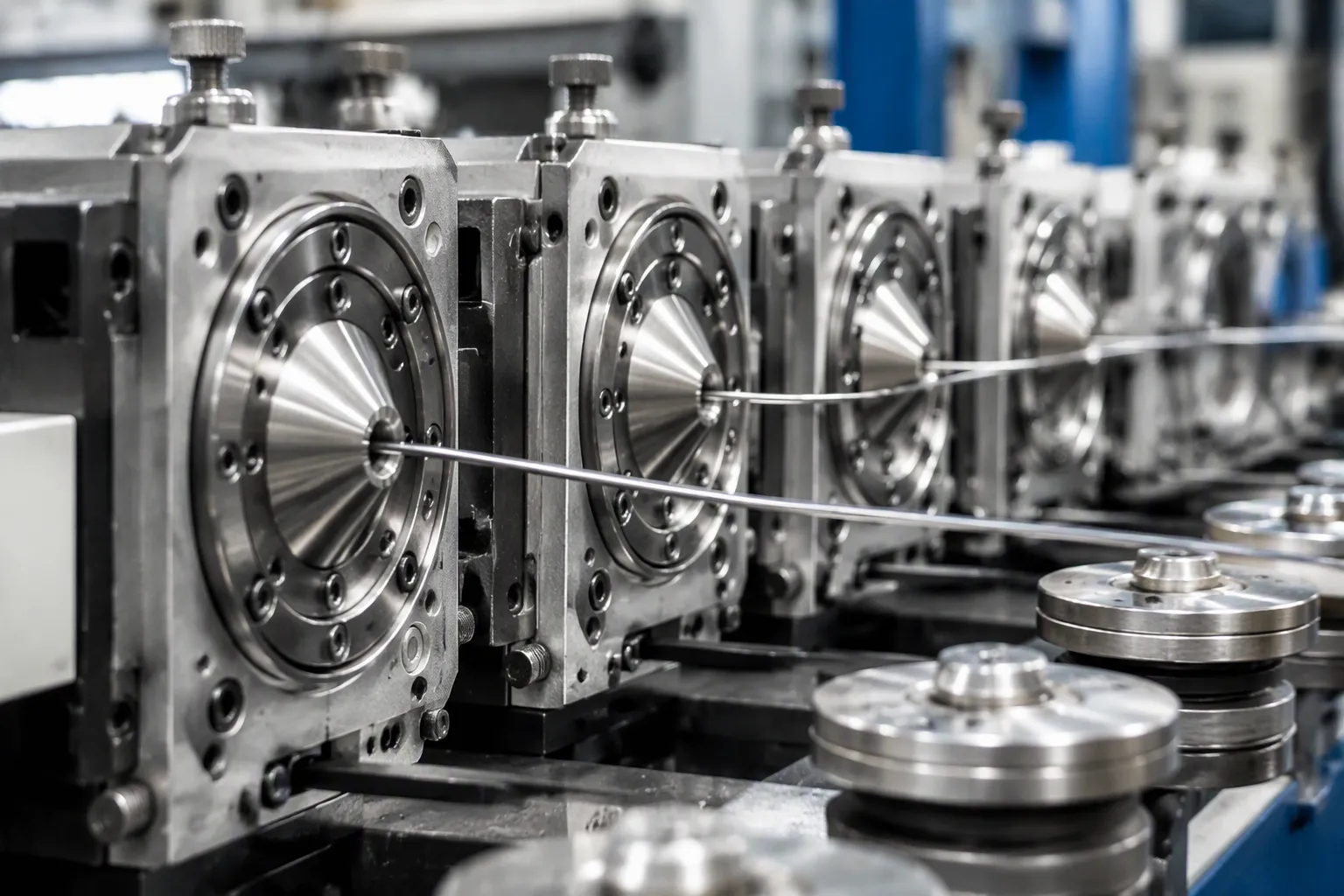
Wire drawing is a cold working process. A metal rod or wire is pulled through a tapered hole in a die, which makes its diameter smaller and gives it excellent surface quality. Each pass shrinks the cross-sectional area, so the wire gets thinner and longer. The reduction ratio, the percentage decrease in cross-sectional area per pass, is the key parameter that controls product quality, production efficiency, and equipment life.
Engineers rarely reach the target diameter in one pull. They use a pass schedule, a series of progressively smaller dies. Keeping each pass within a controlled range limits work hardening and internal stress. Typical schedules look like this:
Process Configuration | Number of Passes | Per-Pass Reduction Ratio |
|---|---|---|
Optimized multi-pass schedule (stress-controlled) | 4–6 passes | 20–25% per pass |
Hitachi multi-pass progressive reduction | 6–10 passes | Optimized per pass to stay below crack-initiation stress thresholds |
Multi-pass (for total reductions > 30%) | Multi-pass configuration | Better energy performance ratio than single pass |
Ratios typically stay within about 15%–30% per pass, and 10%–20% for high-strength grades. Going beyond these ranges invites wire breakage, surface cracks, or center bursts. When the schedule uses up the material's ductility, an intermediate anneal restores it before drawing continues.
Die Design Basics
Die geometry decides how the wire flows through the reduction. Two features matter most: the approach angle and the bearing length. The approach angle is the most influential geometric parameter and varies with material and reduction. The bearing length is the cylindrical land that sizes the wire to its final diameter, usually expressed as a percentage of exit diameter.
Wire Material | Finished Diameter | Recommended Approach Half-Angle | Recommended Bearing Length |
|---|---|---|---|
Copper (magnet wire) | 0.1–0.5 mm | 10°–12° | 25–35% of exit diameter |
Copper (electrical conductor) | 0.5–3 mm | 12°–14° | 35–50% of exit diameter |
High-carbon steel | 0.5–4 mm | 6°–9° | 40–60% of exit diameter |
Stainless steel | 0.3–3 mm | 8°–10° | 40–55% of exit diameter |
Aluminum | 1–5 mm | 14°–18° | 30–45% of exit diameter |
Gold / bonding wire | 0.01–0.05 mm | 8°–12° | 20–30% of exit diameter |
An approach angle below roughly 6° lengthens wire–die contact, which raises friction and heat, speeds up die wear, and scores the wire surface. An angle above roughly 18° concentrates the reduction force at a single point, producing internal chevron cracks and rapid die chipping. Bearing length follows a similar trade-off. A short bearing lowers drawing force and heat and improves finish, but it wears faster. A long bearing maximizes die life and wire straightness, which suits heavy-gauge wire and tight tolerance runs.
Die material selection follows the wire and the duty. Cemented carbide, a tungsten carbide-based composite, offers excellent wear resistance and hardness and sees wide use in wire drawing dies. Diamond and polycrystalline diamond deliver exceptional hardness for fine wire and hard-to-draw materials. Ceramic dies provide strong chemical stability and reduced adhesion to the wire. A cheaper die replaced often can cost more than a durable one, once downtime and scrap from out-of-tolerance wear are counted.
Lubrication and Annealing
Lubricant Types and Delivery
Lubrication controls the friction between the wire and the die. It also limits die wear and protects the surface finish. Two main types are used: wet emulsion lubricants and dry powder lubricants. Wet systems flood the die with fluid, which carries heat away and works well for high-speed drawing above 30 m/s. Dry systems apply powder or soap right onto the wire and are great for low contamination and low disposal costs.
Aspect | Wet Emulsion Lubricants | Dry Powder Lubricants |
|---|---|---|
Friction reduction | Steady; better heat removal, up to 30% faster drawing speeds | Not listed for friction reduction |
Die wear | Less abrasive wear, less frequent die upkeep | More abrasive wear, more frequent die replacement |
Cost trade-off | Higher material cost per unit | Lower material cost, higher die upkeep cost |
Best application | High-speed work where heat removal is key | Work that puts low contamination and disposal costs first |
How the lubricant is delivered matters as much as the type. Wet systems need steady flow, filtration, and concentration control at the die entry. Dry systems need even powder spread and clean wire before entry. Poor delivery creates starved zones, which raise friction and scratch the surface.
Inline Annealing Effects
Cold working hardens the wire and uses up its ductility. Inline annealing brings that ductility back by heating the wire as it moves through the line. This process relieves internal stress and regrows the grain structure. Hardness drops from 494 Hv to 261 Hv, a level close to vacuum furnace annealing at 780 °C. Strength falls and elongation rises to 25–40% or higher.
The benefits go beyond softness. Even heating along the coil gives consistent properties through the length and cross-section. Electrical conductivity improves a little as lattice defects relax. Fatigue resistance goes up, so the wire survives repeated flexing during stranding and cabling. Controlled atmosphere limits oxidation and keeps the surface bright. Annealing is the bridge between wire drawing and the stranding stage.
Wire Drawing Quality Control
Inline Monitoring and Defects
Three kinds of defects are most common in wire drawing: surface scratches, diameter variation, and wire breaks. Each one has a specific cause. Scratches come from worn dies or areas with too little lubrication. Diameter variation comes from die wear or pulling speed that is not steady. Breaks come from reduction ratios that are too high or internal cracks that grow with each pass.
Inline monitoring catches these problems before they reach the take-up reel. A one-axis laser diameter system tracks die wear and confirms the process is stable. A two-axis system measures two perpendicular axes, which allows accurate ovality calculation. The combined diameter and surface defect system adds high-speed detection of lumps and neckdowns. Magnetic flux leakage, eddy current, ultrasonic, and laser-based inspection all work for finding surface cracks.
Temperature control during drawing is critical. Thermal stress causes surface cracking, so monitoring systems must keep processing conditions steady through the whole operation.
Defect
Inline Detection Method
Diameter drift
Laser sensors measuring on three axes at high sample rates
Ovality
Two-axis diameter measurement
Die wear
One-axis diameter monitoring
Surface cracking
Magnetic flux leakage, eddy current, ultrasonic, laser inspection
Laboratory Testing
Inline data tells operators what is happening right now. Laboratory testing confirms what the wire actually is. Tensile testing and elongation measurement establish mechanical properties. Conductivity measurement verifies electrical performance after annealing. Surface inspection checks roughness for high-quality wire.
Dimensional accuracy deserves its own check. Precision wire usually holds diameter variation within ±0.01 mm. Hardness uniformity across the cross-section should stay within HV 20–30 variation. Microstructural review confirms grain structure uniformity and flags internal cracks. Eddy current and ultrasonic protocols cover internal integrity. International frameworks such as ISO 16120 for steel wire and ASTM B258 for aluminum wire anchor the whole test program. Together, inline diameter measurement and laboratory verification form a closed loop of quality control in wire drawing.
Inside the Cable Extrusion Line
Extruder Components and Screw Zones
A cable extrusion line has four main parts. The hopper holds polymer pellets and feeds them by gravity. The barrel surrounds the screw and has heaters that soften the plastic. The screw turns inside the barrel and pushes material forward. The head holds the crosshead and die, where the melt wraps around the conductor. These key parts of a cable extrusion line work as one system, and each one affects melt quality.
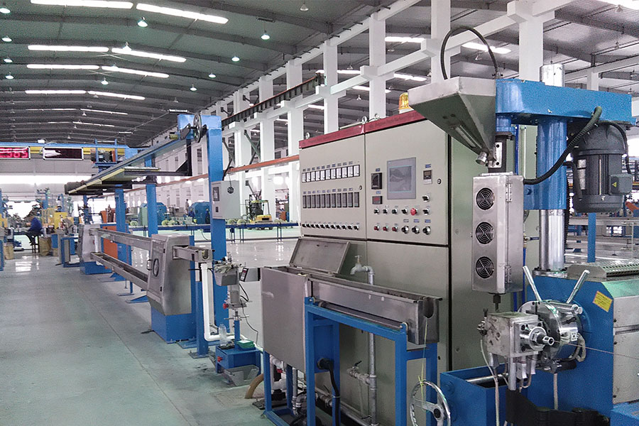
The screw itself splits into three zones, and each zone does a different job:
Feed zone: flight depth stays the same. This deep-flighted section takes in pellets and moves them forward.
Compression zone: flight depth drops a lot. The thermoplastic gets squeezed here and plastication starts.
Metering zone: flight depth is steady again but shallower than the feed zone. The force it makes pushes the melt through the shaping die.
Operators set the metering zone a little above the compression zone temperature. This setting melts any solids left and mixes the polymer well. Steady melt pressure at the crosshead and die keeps wall thickness even along the whole run.
Die Types Compared
Three die designs are most common in cable extrusion, and each one fits different products. The table below compares them.
Method | Inner die | Outer die | Die-eye distance | Key advantages | Typical applications |
|---|---|---|---|---|---|
Pressure | Generally flat | Pressurized, with ~2–5 mm gallery section | Relatively far apart | Tight adhesion, smooth appearance | SVT, SJT, H05VV external jackets; most core wires |
Semi-tube | Tube (~3–5 mm) | Common type | ~1–2 mm | Good peelability, uniform thickness, soft wire | Braided or shielded wires |
Tube | Tubular (~5–10 mm long) | Ordinary, no pressure; oversized (~1.2–1.5× finished OD) | Inner die extends beyond or flush with outer die | Soft wire, very uniform thickness | High-frequency wires such as UL1394, HDMI, UTP |
Pressure dies give strong adhesion for insulation or sheathing on standard core wires. Semi-tube dies balance adhesion and peelability for shielded constructions. Tube dies protect soft conductors and give very even walls on high-frequency cables. A well-matched die choice keeps every cable extrusion line running at its best, and the same logic applies across cable extrusion lines that serve different product families.
Cooling and Take-Up
Cooling Trough Profiles
Cooling troughs harden the hot melted plastic in steps. This step-by-step cooling stops holes, oval shapes, and shrink marks from forming in the insulation. Water temperature usually stays between 15 and 30°C. If the cable is not cooled enough, the insulation can end up with surface flaws. Cooling it too fast can cause leftover stress or shrink holes, especially in thick insulation walls.
Trough length has to match line speed and insulation wall thickness. Cable that is not cooled enough will fail quality checks later on. A common industry rule is about 1 meter of trough for every 1 mm of insulation wall thickness, for each 10 m/min of line speed. Fast lines making fine wire may need pressurized water cooling or air quench systems instead. Operators often keep the first stage warm and later stages cooler, so the melt cools down gently instead of getting a shock.
Tension and Winding Control
Take-up tension decides whether the finished cable keeps its shape. Too much tension flattens the insulation and makes it oval. Too little tension lets the cable wind loosely and cross over itself on the spool. A dancer or load-cell feedback loop keeps tension steady as the reel fills up. The control system adjusts for the growing package diameter, so the pull stays even from the core to the surface.
Winding control works with tension to protect the product. Traverse guides lay the cable in even layers and stop it from piling up at the flanges. Steady layer spacing prevents pressure marks on soft insulation. Together, tension and winding protect the round shape that diameter measurement confirms at the end of the line. Good ovality control at take-up also keeps later connector and jacket steps running smoothly. A stable take-up stage finishes the extrusion line with product that meets its size spec.
Extrusion Quality Control
Inline Monitoring and Defects
Quality control in cable extrusion lines directly shapes performance, safety, and reliability. A thin wall, a pinhole, or a scorch mark can fail a spark test or shorten service life in the field. So operators treat extrusion quality control as an ongoing habit, not just a final check.
Temperature control is at the heart of most extrusion defects. A melt temperature that is too low leaves resin not fully melted. Unmelted particles and high extrusion pressure then cause a rough cable surface. The fix is to check barrel-zone and head temperatures against the material's recommended processing window. Find the zone with weak melting instead of raising every zone.
Poor melting has several causes. Temperature control may be too low or not right. Hard melted resin particles may sit in the plastic. The screw and pulling speed may run too fast for full melting. Uneven mixing during granulation or poor raw material quality can also play a part. Remedies include controlling temperature per process rules, slowing screw and traction speed to lengthen heating time, using screw cooling water, and picking a suitably small mold sleeve to strengthen rubber-mouth pressure.
Overheating brings its own problems. A melt temperature that is too high reduces stability or starts degradation. This shows as discoloration, odor, black specks, or smoke. Scorch comes from ultra-high temperature control, a faulty temperature instrument, a screw left uncleaned for long periods, too much heating time, or a loose head gland. Remedies include checking the heating system, cleaning the screw and head regularly, following heating time limits, and cleaning the head and screw at once when scorch appears.
Bubbles and voids need a careful diagnosis. Too much temperature degrades the polymer and makes gas, often with a burnt smell and black particles. Moisture in the resin also turns to vapor during extrusion. The fix differs by cause: reduce overheating in the first case, and check drying temperature, drying time, dryer performance, and material storage in the second.
Defect | Temperature / Plasticization Cause | Remedy |
|---|---|---|
Rough cable surface | Melt temperature too low, incomplete plasticization, poor flow through head and die | Verify barrel-zone and head temperatures against the material window; find the weak zone rather than raising all zones |
Rough cable surface | Extrusion temperature too high, reduced melt stability or degradation | Check for discoloration, odor, black specks, or smoke and correct the overheating |
Bubbles / voids | Excessive temperature degrading polymer and generating gas | Inspect thermal history and reduce overheating; distinguish from moisture bubbles |
Bubbles / voids | Moisture in resin vaporizing during extrusion | Check drying temperature, drying time, dryer performance, and storage |
Burnt material / scorch | Excessive temperature, long residence time, dead zones, degraded residue | Check the heating system, clean screw and head regularly, avoid long heating and parking time |
Diameter Measurement and Defect Detection Solutions
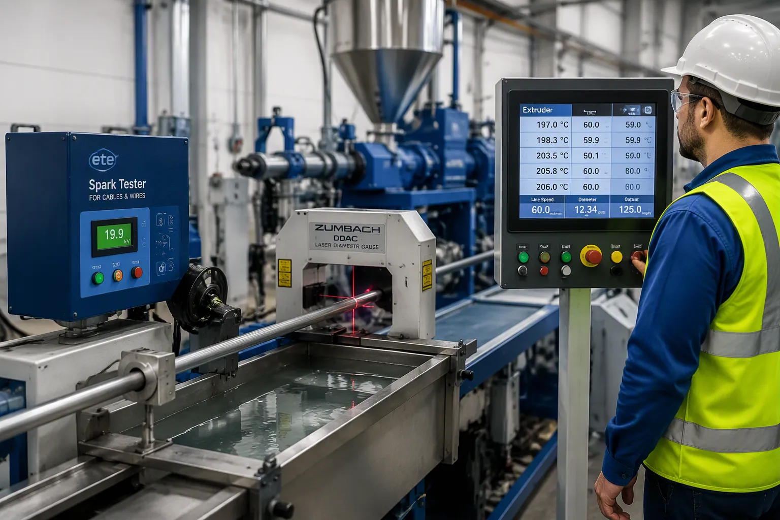
Diameter measurement and defect detection solutions turn quality control from a batch check into a running process. A laser diameter gauge sits after the cooling trough. It gives continuous outer-diameter readings that feed back into line control. Drift gets caught before a bad drum leaves the line. This inline diameter measurement supports diameter consistency across the full run.
Capacitance gauges add a second layer. Real-time capacitance monitoring measures insulation geometry, dielectric consistency, and concentricity during extrusion rather than after reeling. Early-warning detection flags wall-thickness, dielectric, material, and concentricity deviations the moment they occur. Closed-loop process control then integrates through CANbus with a controller for capacitance-driven correction. On-board SRL and FFT analysis forecasts finished-cable electrical compliance against standards such as IEC 61156 and TIA/EIA 568. The system also delivers full electrical performance traceability across every meter produced.
Spark testers close the loop on pinholes and insulation faults. The finished cable runs through a high-voltage electrode array, and any fault trips the line. Premium and medical lines may add optional wall-thickness and concentricity gauges, with laser measurement holding walls to micron tolerance.
In the conductor insulation step, a laser gauge and spark tester close the loop on diameter and pinholes, while the testing stage combines a spark tester, laser gauge, and capacitance meter for inline integrity and dimension control.
The net effect is simple. Measurement converts quality control into a running process, so drift is corrected before scrap is made. Diameter measurement systems also support ovality control at take-up, where a consistent diameter confirms the round shape that later connector and jacket steps need. Together these tools support producing high-quality cables with fewer field failures.
Operators should treat a short list of key parameters to monitor during production as the backbone of the line log: melt temperature by zone, extrusion pressure, line speed, and diameter. A cable extrusion line that tracks these values can hold consistent product quality across long runs. Cable extrusion demands steady monitoring at every stage. The same logic applies across cable extrusion lines that serve different product families. Every cable extrusion line benefits from a disciplined response to diameter variations and surface flaws. Cable extrusion rewards that discipline with fewer rejects and steadier output.
Extruder Configurations Compared
Single-Screw, Twin-Screw, Tandem
Each setup moves, melts, and mixes the polymer in its own way. The table below compares the main options on the strengths that matter most in cable extrusion.
Configuration | Conveying Mechanism | Mixing Strength | Typical L/D | Energy Use (Simple Melting) | Best-Suited Materials |
|---|---|---|---|---|---|
Single screw | Drag flow, friction-dependent | Low to moderate distributive, poor dispersive | 24:1 to 36:1 | Best, 0.15–0.30 kWh/kg | Pre-compounded PE, PP, PS, PET pellets |
Co-rotating parallel twin | Positive displacement, self-wiping | Excellent distributive and dispersive | 32:1 to 52:1 | 0.25–0.40 kWh/kg | Filled compounds, masterbatch, engineering blends |
Counter-rotating twin | Positive displacement, enclosed C-chambers | Moderate distributive, low to moderate dispersive | 10:1 to 22:1 | 0.18–0.28 kWh/kg | PVC dry blend, powder coatings |
Conical twin | Positive displacement, tapered C-chambers | Moderate distributive, low dispersive | 12:1 to 18:1 | 0.12–0.22 kWh/kg | PVC pipe and profile, WPC, recycled PVC |
Tandem line | Twin screw primary plus single screw secondary | Excellent in the primary stage | Varies by stage | Moderate | Foam (PS, PE, PP), highly filled systems |
A single screw gives the best mix of simple design, dependability, and low cost. It makes up most installed capacity and fits high-volume, steady work like wire and cable coating. In that work, steady melt delivery and stable pressure are what count. Its weaker mixing becomes a problem when filler loads are high or color must match tightly.
Matching Configuration to Product
The material and the product type decide which setup fits. A single screw runs PE and PP film and pipe from pellets at the lowest operating cost. Co-rotating parallel twin screws do best with filled PP compounds above 30% by weight, engineering blends such as PC/ABS, and color masterbatch. Conical twin screws handle the uneven bulk density of recycled PVC and take in low-density wood flour for WPC. Tandem lines solve the conflicting heat needs of foam sheet. They melt hard in the primary stage, then cool to an exact foaming temperature in the secondary.
These choices apply across common wire and cable extrusion processes. For silicone constructions, extrusion and curing must work as one controlled process. The screw design must match the polymer, and screen packs must balance shear against contamination. Temperature settings matter too. A setting that is too high burns material and traps gas voids, while one that is too low leaves a non-smooth surface. Every cable extrusion line gains from this discipline, and lines that match setup to material give steadier output. Careful extrusion planning keeps any cable extrusion line reliable.
Material Considerations
Polymer Selection Criteria
Engineers pick insulation and jacketing polymers based on what the installed cable must handle. Four criteria guide most choices. Flexibility makes installation easier in tight spaces and is key in moving applications like robotic arms, where stiff cables wear out fast. Environmental durability means resisting moisture, chemicals, oil, fire, and UV light. Thermal properties must hold up in hot and cold extremes without melting or becoming brittle. Stripability matters at termination and splicing, where technicians must remove material cleanly.
Compound formulation shapes these properties. A base polymer carries fillers, plasticizers, antioxidants, antiozonants, UV stabilizers, pigments, and curing agents or accelerators. Additive levels vary widely. Polymer content can be as low as about 30% in some elastomeric sheathing compounds and as high as about 97% in MV/HV XLPE insulation. The service environment sets the target. Temperature, water buildup, corrosive substances, mechanical stress, rodents, mold, and sunlight all attack the cable over its life.
Material-Process Compatibility
Polymer choice affects every setting on the line. A material with a narrow processing window needs tighter temperature control during cable extrusion. Screw design must match the polymer's melting behavior and shear sensitivity. Cooling profiles follow the melt's crystallization and stress-relief needs. A compound that runs well on one extruder may struggle on another, so processors validate each material against the actual equipment.
The three polymer families behave differently. Thermoplastics soften on heating and reflow, thermosets cross-link and hold their shape, and fluoropolymers bring high thermal and chemical resistance. Each family carries its own product variations. Matching material to process keeps extrusion stable and protects the finished insulation or sheathing. Processors who align polymer, screw, temperature, and cooling on their cable extrusion lines see fewer defects and steadier output. Careful material selection therefore supports reliable cable extrusion from the first pass to the last.
Keeping dies and lubricants under control keeps wire drawing steady. Keeping temperature, pressure, and cooling under control keeps cable extrusion steady. Together, these two processes set the quality limit for the whole line.
Quality control is an ongoing job done inline at every stage. Careful laboratory testing backs it up. It is not just a final inspection step.
Process control connects directly to how reliable the final product is. Consistent conductor dimensions, insulation with no defects, and proven electrical and mechanical performance all come from it. Tighter process monitoring and diameter measurement and defect detection solutions support higher cable reliability and fewer field failures. That discipline makes wire drawing and cable extrusion a dependable path to producing high-quality cables.
FAQ
What reduction ratio should a drawing pass schedule use?
A pass schedule keeps each reduction inside a set range. The article gives about 15%–30% per pass for general wire and 10%–20% for high-strength grades. Going past those ranges can cause breakage, surface cracks, or center bursts. An intermediate anneal brings back ductility when the schedule uses up the material.
Why does a drawing die's approach angle matter?
The approach angle controls how the wire flows through the reduction. An angle below about 6° makes contact longer, raises friction and heat, and scores the surface. An angle above about 18° puts force at one point and causes internal chevron cracks. Matching the angle to material and reduction protects both wire and die.
When should an operator choose a pressure die over a tube die?
Pressure dies suit standard core wires and external jackets, where tight adhesion and a smooth look matter. Tube dies protect soft conductors and give very even walls on high-frequency cables. Semi-tube dies balance adhesion and peelability for braided or shielded constructions. Product construction and conductor stiffness guide the choice.
What causes a rough cable surface during extrusion?
A melt temperature that is too low leaves resin not fully melted, so unmelted particles and high pressure roughen the surface. Too much temperature lowers melt stability and can break down the polymer. Operators should check barrel-zone and head temperatures against the material window and find the weak zone rather than raising every zone.
How does inline measurement support extrusion quality control?
A laser diameter gauge after the cooling trough gives continuous outer-diameter readings that feed back into line control. Capacitance gauges track insulation geometry and concentricity in real time. Spark testers catch pinholes and insulation faults. Together these tools fix drift before scrap is made, rather than after reeling.


I want to comment
Recent News
1.RELBJ100-12 Automatic Hydraulic Drawing and Straightening Machine
2021-10-122.Sixteen-head Wire Drawing Continuous Annealing Production Line
2021-05-083.Double-wire Intermediate Wire Drawing Continuous Annealing Production Line
2021-04-074.Multi-head Copper Wires Drawing Machine with Anealer
2021-05-205.Multi-head Wire Drawing Continuous Annealing Production Line
2022-09-296.Multi-head Wire Drawing Continuous Annealing Production Line
2024-01-087.Continuous Aluminum Extrusion Production Line
2021-08-238.Insulation and Sheathing Extrusion Production Line
2021-03-309.How to Build a Connected Wire & Cable Production Line Without Downtime: From Bunching to Extrusion
2026-10-1410.What Is a Cable Extrusion Machine and How Does It Work
2026-10-21





View More(Total0)Comment lists